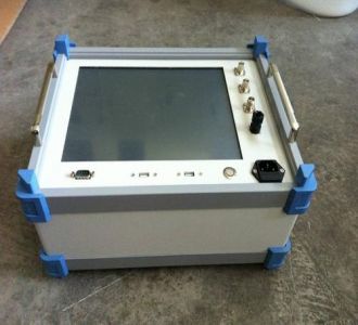

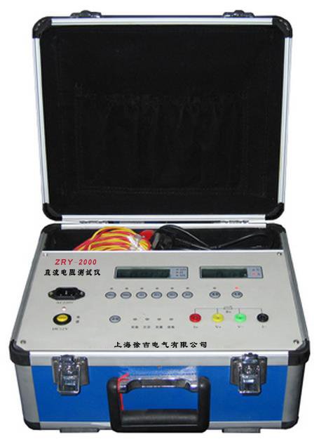
Dielectric Loss Tester
Analysis completed, referencing 6 documents in total
The Dielectric Loss Tester (abbreviated as tan delta tester, English: Dielectric Loss Factor Tester / Tan Delta Tester) is a high-precision special instrument used to measure the dielectric loss factor (tanδ) and capacitance (Cx) of insulation in high-voltage electrical equipment. It is a core testing tool in preventive tests of power systems for evaluating the insulation condition of equipment, and is known as the "diagnostic expert" for insulation performance.
Working Principle
Modern dielectric loss testers mainly adopt the vector calculation method: the internal inverter generates a test high-voltage source, which is applied to the test object through a step-up transformer, while a built-in high-stability standard capacitor forms a standard circuit. High-precision acquisition circuits measure the amplitude and phase difference of the current in the standard circuit and the test object circuit respectively. Using digital signal processing (DSP) and fast Fourier transform (FFT) technology, the capacitance value (Cx) and dielectric loss tangent (tanδ) of the test object are calculated in real time.
To cope with strong electric field interference in substations, the instrument generally adopts frequency conversion anti-interference technology, outputting 45Hz/55Hz or 55Hz/65Hz heterodyne sine waves to automatically avoid 50Hz power frequency interference, fundamentally solving the problem of accurate measurement in strong electric field environments.
Core Measurement Parameters
Table
Download as table
Export as image
Parameter Meaning Diagnostic Significance
Dielectric loss factor (tanδ) Dimensionless ratio of energy loss degree of insulating material under alternating electric field The larger the value, the more severe the moisture, aging, and deterioration of the insulation. It is the most sensitive indicator for judging insulation condition.
Capacitance (Cx) Equivalent capacitance value of the test equipment When damp, capacitance increases; when aged and dried, capacitance decreases. Significant changes may indicate internal component breakdown or open circuit.
In simple terms, "tanδ" indicates the "quality" of the insulating material, while "Cx" indicates the "state" of the insulation structure.
Main Technical Parameters
Table
Download as table
Export as image
Item Parameter
High voltage output 0.5kV~10kV, multi-gear adjustable or continuously smooth adjustment
Output frequency 45Hz/55Hz, 55Hz/65Hz and other heterodyne frequencies, supports 50Hz/60Hz
tanδ measurement range 0~1 (resolution 0.0001)
Capacitance measurement range 3pF~60000pF (internal connection), external connection up to ≤10μF
tanδ measurement accuracy ±(1% reading + 0.04%)~±(1.5% ± 0.09%)
Capacitance accuracy ±(1% reading + 5pF)~±(1.5% ± 2pF)
Working power supply AC 220V±10%, 50Hz±1Hz
Working temperature -5℃~40℃ (some models -15℃~50℃)
Relative humidity 30%~85% (some models <90%)
Instrument weight Approximately 16kg~30kg
Output power 0.6kVA~1.5kVA
Data storage 100~255 groups, supports U-disk export
Test Methods
Table
Download as table
Export as image
Method Applicable Scenario Features
Direct connection method Test object insulated from ground (such as bushings, capacitors) High accuracy, used when test object is not grounded
Reverse connection method One end of test object directly grounded (such as transformer winding to ground) Most commonly used on site, adapts to grounded equipment
External connection method Requires external standard capacitor and voltage regulator Suitable for large capacitance test objects or special requirements
CVT self-excitation method Capacitive voltage transformer (CVT) Simultaneously measures tanδ and capacitance of C1 and C2 with one connection
Core Functional Features
Fully automatic measurement: microprocessor controlled, one-key completion of voltage boosting, measurement, and voltage reduction process, with Chinese menu prompts for operation
Frequency conversion anti-interference: adopts heterodyne technology + digital notch filtering, capable of accurate measurement in strong interference sites up to 500kV and below
CVT special testing: supports simultaneous measurement of C1/C2, measurement without disconnecting high-voltage leads, reverse connection low-voltage shielding to measure C0, and automatic compensation for busbar grounding effects
Multi-function integration: some high-end models integrate CVT ratio measurement, LCR automatic measurement, insulation resistance testing (polarization index/absorption ratio) and other functions
Multiple safety protections: high-voltage short circuit/breakdown/overcurrent protection, voltage boost locked when not grounded, anti-misoperation, electric shock protection (automatic high-voltage cutoff), emergency stop button
Data management: large-screen Chinese LCD display (some are touch screens), built-in micro printer, supports U-disk export and host computer software management
Typical Application Scenarios
Table
Download as table
Export as image
Equipment Type Test Content Diagnostic Purpose
Power transformer tanδ and capacitance between windings and between winding and ground Assess the condition of transformer oil and overall insulation
Capacitive voltage transformer (CVT) tanδ and capacitance of C1 and C2 Detect deterioration or moisture of capacitor elements
High-voltage bushing tanδ and capacitance between core rod and last screen Determine whether the bushing is damp or aged
Current/voltage transformer Insulation from primary to secondary and ground Evaluate insulation performance of transformer
High-voltage cable tanδ between core wire and shielding layer Evaluate insulation aging condition of cable
Coupling capacitor tanδ and capacitance Regularly monitor insulation performance
Insulating oil Measure oil dielectric loss with standard oil cup Determine whether oil quality has deteriorated
Generator Insulation loss of stator winding Evaluate insulation condition of generator
Result Determination Methods
tanδ value: compare longitudinally with historical data; even if not exceeding the limit, a significant increasing trend should be taken seriously; compare horizontally with similar equipment; if the difference is too large, investigation is needed
Capacitance Cx: for capacitive equipment, capacitance change generally should not exceed ±5%; if exceeded, internal component defects should be suspected
Temperature correction: tanδ value is greatly affected by temperature; when analyzing results, it should be converted to the same temperature for comparison
Test conditions: ambient temperature not lower than 5℃, humidity not greater than 80%, test object must be de-energized, grounded, fully discharged, and surface cleaned
Executive Standards
Table
Download as table
Export as image
Standard Number Name
DL/T 962-2005 General Technical Conditions for High Voltage Dielectric Loss Tester
GB/T 20833.3-2018 Standards related to dielectric loss factor measurement
GB/T 5654-2007 Methods for measurement of power-frequency relative permittivity, dielectric loss factor and DC resistivity of liquid insulating materials
GB/T 31838 series Dielectric and resistive properties of solid insulating materials
JJG 116 Verification Regulation of Dielectric Loss Factor Tester
Operation Points
Safety first: strictly implement the procedures of power outage, voltage verification, and grounding wire installation; confirm that the test object is completely de-energized and fully discharged
Reliable grounding: the grounding terminal of the instrument must be reliably grounded; when not grounded, the instrument should be locked to prohibit voltage boosting
Correct wiring: in direct connection method, UH terminal is high voltage; in reverse connection method, IX terminal is high voltage; high-voltage cables must maintain sufficient distance from ground
Strictly prohibit switching during power-on: strictly prohibit operating the test voltage selection switch during measurement
Discharge after test: after testing, first cut off power, then fully discharge the test object
Use original cables: use the special test cables provided by the manufacturer as much as possible to ensure measurement accuracy