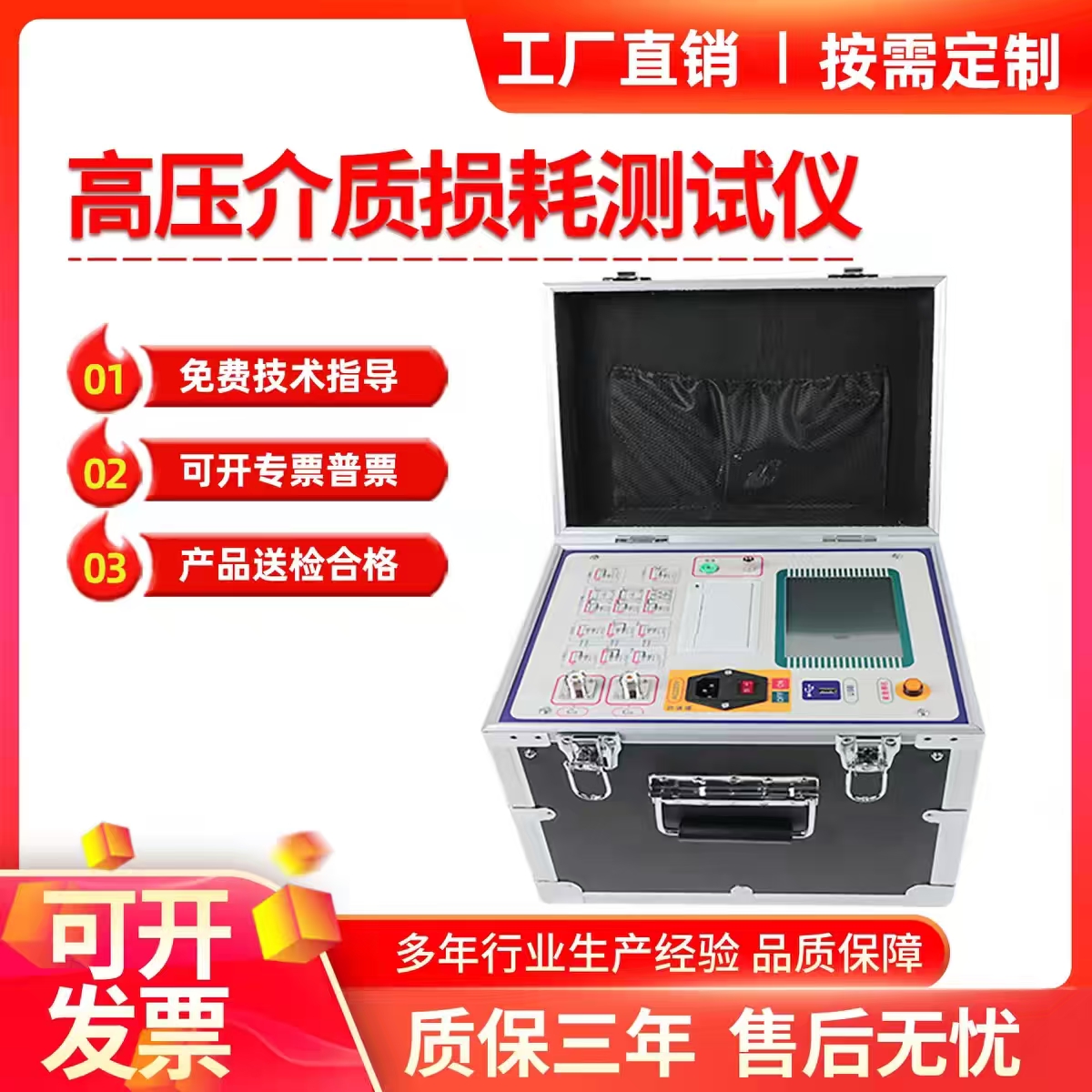

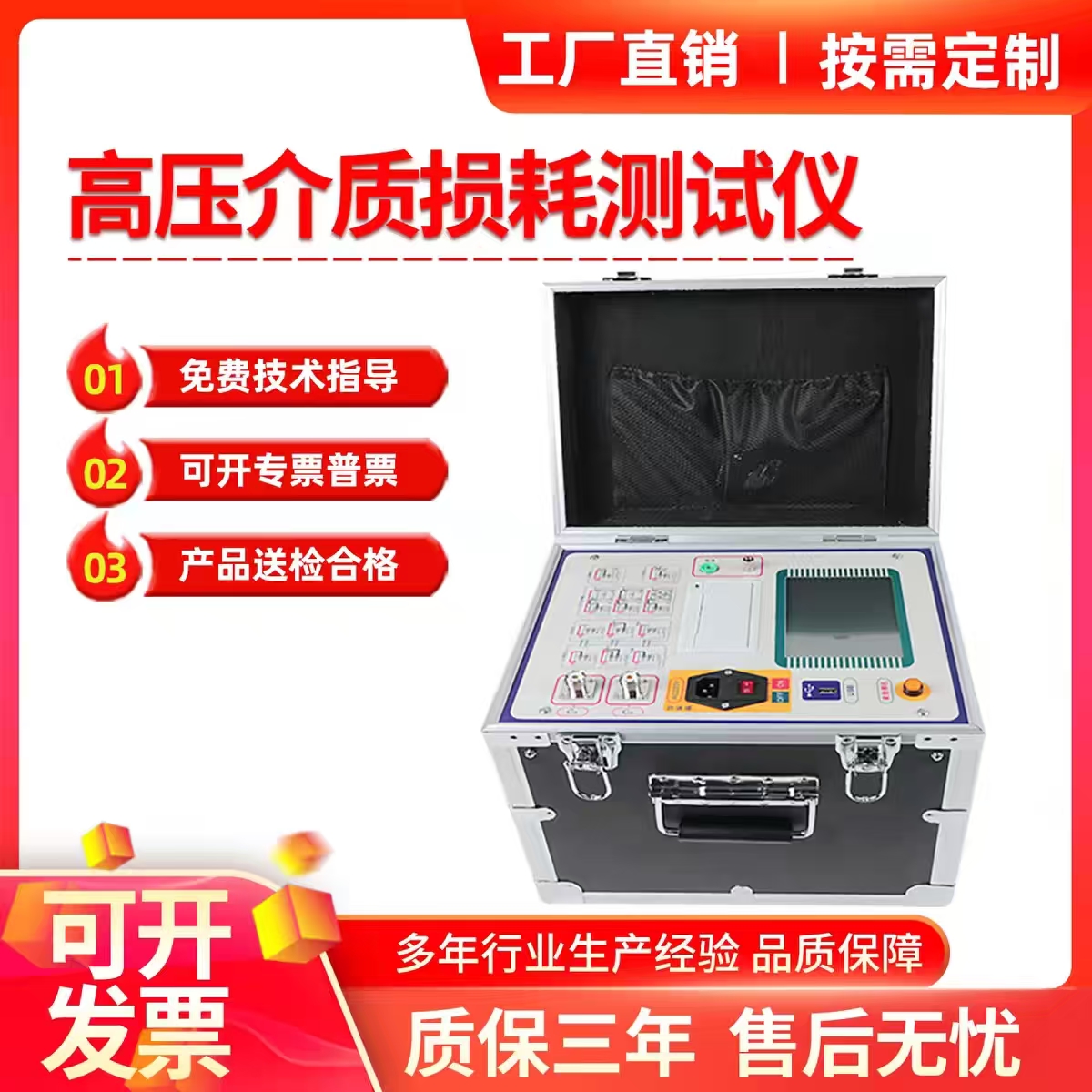
Dielectric Loss Tester
The dielectric loss tester (often referred to as the "tan delta tester") is a "diagnostic expert" for the insulation performance of electrical equipment. It is mainly used to accurately assess the insulation condition of high-voltage electrical equipment without damaging it, making it a core tool for preventive testing and fault diagnosis in power systems.
The following is a detailed introduction to the dielectric loss tester:
I. Core Measurement Parameters and Principles
The core task of the dielectric loss tester is to precisely measure two key parameters to determine the degree of insulation deterioration:
Dielectric loss factor (tgδ): A physical quantity that characterizes the degree of energy loss of insulating materials under an alternating electric field. Pure, dry, and intact insulating materials have a very small tgδ value; however, when the insulation is damp, aged, cracked, or contains impurities, energy loss increases, and the tgδ value significantly rises.
Capacitance (Cx): Reflects the overall condition of the insulated equipment. For example, after internal moisture ingress, the capacitance value typically increases; aging or drying of insulation may lead to a decrease in capacitance; for capacitive equipment, a significant change in capacitance may indicate internal component breakdown or short circuit.
II. Main Functions and Technical Features
Modern fully automatic anti-interference dielectric loss testers feature high integration and intelligence:
Strong anti-interference capability: Utilizes frequency conversion technology (heterodyne measurement method, e.g., outputting 45Hz/55Hz signals) and digital filtering technology to effectively avoid power frequency interference, ensuring accurate measurement in strong electric field environments (such as substation sites).
Multiple wiring modes: Supports the normal connection method (for testing ungrounded specimens), the reverse connection method (for testing directly grounded specimens), and the CVT self-excitation method (for measuring capacitor voltage transformers without an external high-voltage source).
Automation and safety: Built-in high-voltage power supply and standard capacitor, with the entire measurement process automatically controlled by a microprocessor, and comprehensive safety protection measures such as overcurrent, overvoltage, and breakdown protection.
III. Core Application Scenarios
Dielectric loss testers are widely used in power plants, substations, electrical laboratories, and other scenarios to "inspect" the following high-voltage equipment:
Capacitive equipment: Capacitor voltage transformers (CVT), high-voltage bushings, coupling capacitors, etc.
Transformer-type equipment: Power transformers (measuring dielectric loss and capacitance between windings and between windings and ground), voltage transformers (PT), and current transformers (CT).
Other high-voltage equipment: High-voltage cables, surge arresters, generator stator windings, etc.
Insulating oil testing: With a dedicated oil test cell, it can precisely measure the dielectric loss factor of insulating oil to determine whether the oil quality has deteriorated.
IV. Selection and Usage Precautions
Equipment selection: Comprehensive consideration should be given to measurement accuracy, measurement range, anti-interference capability, and portability. For strong electromagnetic interference environments, frequency conversion anti-interference technology is a core evaluation indicator.
Environmental impact: Temperature has a significant effect on the dielectric loss factor; the tgδ value of insulating materials typically increases with rising temperature. During testing, the ambient temperature should be recorded, and results should be converted to a standard temperature (e.g., 20°C) using empirical formulas or manufacturer coefficient tables for comparison.
Abnormal data troubleshooting: If the test result shows a negative value, it is usually not due to the insulation "generating energy," but rather caused by strong on-site electric field interference, stray capacitance effects due to the specimen's small capacitance, or phase calibration deviation of the instrument. In such cases, frequency conversion anti-interference technology, shielding the specimen surface, or checking the grounding status should be employed to resolve the issue.